My First Instruction
First instruction is probably going to be unlike any other in the amount of work that I’ll need to put into implementing it, so it deserves a post on its own. Let’s start from the RV32I description in the (currently) latest version of the RISC-V ISA Specification, which is given in the Chapter 2: RV32I Base Integer Instruction Set. The specification first goes on to describe Integer Computational Instructions (Chapter 2.4), of which the addi instruction is explained first, so let’s start with that one.
Relevant pygears_riscv git commit: pygears_riscv@a7d98ec
All RV32I instructions are encoded with 32 bits using several formats (although there is also a Compressed Instruction Formats (Chapter 12.2) but I’ll leave that for later). All the information needed for the instruction execution has to be encoded in 32 bits and these formats specify where exactly is each peace of information located within these 32 bits. Usually the instruction needs to specify which operation to perform (opcode and funct fields), which registers are involved (rs - register source or rd - register destination), and usually provides some immediate values as arguments (imm fields). One of the key advantages of the RISC-V ISA is that pieces of information of the same type (like rd field) are usually located at the same position within the 32 bit encoding for different formats, which proved to simplify the hardware implementation.
For RV32I, a set of 32 registers is needed, named x0 - x31, where x0 is different from the others in that it has a fixed value of 0, i.e it’s value cannot be changed. The ISA specification defines the XLEN parameter to represent the width of the registers in number of bits: either 32 or 64. I’ll try to keep XLEN a design parameter of the processor implementation, but I’ll first focus on a version with XLEN=32, i.e with the processor version with 32 bit wide registers.
Instruction format
The addi instruction has an “Integer Register-Immediate” format, aka the “I-type” format shown below. The instruction is executed by adding the value of the 12 bit immediate field imm to the value read from the register specified by the rs1 field. The result is then truncated to XLEN bits and stored into the register specified by the rd field.
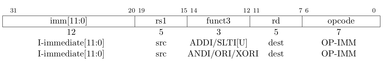
“Integer Register-Immediate” instruction format, aka the “I-type” format, from the RISC-V ISA Specification
Since the instruction encodings have fields that serve different purposes from one another, I’ll represent the instruction with the typing/tuple PyGears type. The typing/tuple type represents a generic heterogeneous container type akin to records and structs in other HDLs, and I can specify the names and types of the fields by providing a Python dict in square brackets which maps field names to the field types. For the “I-type” instructions, I ended-up with a following definition in PyGears, given in pygears_riscv/riscv/riscv.py:
-
TInstructionI¶ TInstructionI = Tuple[{ 'opcode': Uint[7], 'rd' : Uint[5], 'funct3': Uint[3], 'rs1' : Uint[5], 'imm' : Int[12] }]
The opcode and funct3 fields determine the function to be executed, and rd, rs1 and imm fields carry the function arguments. The opcode and funct3 fields store the ID of the function, so I can represent them with an unsigned number, i.e the typing/uint PyGears type. An enumerated type might constrain this fields better, since not all function IDs might be available in a specific processor implementation (after this blog post I will have implemented only one function - addi). However, PyGears doesn’t yet have enumerated types, so I’ll use the typing/uint type as the second best.
Values of the rs1 and rd fields contain the IDs of the registers involved, hence they are 5 bit wide so that they can encode all 32 register IDs, hence they are represented by the Uint[5] type. ISA specifies that addi as a signed operation, and that the values in the imm field are encoded as signed integers, so I’ll use Int[12] type here.
Now any gear that operates on the imm field can, if needed, automatically adjust its operation to handle the signed numbers correctly, and I don’t have to worry about it for every gear explicitly. This is a major advantage of the typing system, since I can express my intents using the type (like with Int here) in a single place in the code, and this intent will propagate automatically throughout the design. Traditional HDLs offer only rudimentary typing support, so you need to follow you signals around and explicitly. However, just specifying the type is only a half of the story. The other half lies in providing the polymorphic behavior for the modules, so that they automatically accommodate for different data types.
OK, so now we have the TInstructionI type, that describes the general format for the “I-type” instructions, and my addi instruction will be an instance of this type. As I said, opcode and funct3 will have unique, specific value for the addi instruction which is specified by ISA. I had to consult Chapter 19: RV32/64G Instruction Set Listings in order to get the correct values for the function ID fields: opcode=0x13 and funct3=0x0.

addi instruction format, from RISC-V ISA Specification
Other instruction fields: rd, rs1 and imm, can take arbitrary values, so I can’t fix those in advance. This gives me the following template for the addi instruction:
-
OPCODE_IMM¶ OPCODE_IMM = 0x13
-
FUNCT3_ADDI¶ FUNCT3_ADDI = 0x0
-
ADDI¶ ADDI = TInstructionI({ 'opcode': OPCODE_IMM, 'rd' : 0, 'funct3': FUNCT3_ADDI, 'rs1' : 0, 'imm' : 0 })
Since PyGears doesn’t have templates for type instances, all I can do is assign some default values to the fields whose values can change. Maybe its worth considering whether true generic templates (with generic parameters) for the type instances would add anything of value (or researching if there are languages that support these). In that case, instead of zeros above, the fields would be assigned some template placeholder names, that would need to be assigned values later. Prolog does something like that?
Processor implementation
Since the idea of this blog series is to show how one can evolve a complex hardware design using PyGears without wasted effort, by implementing one feature at a time, I will turn a blind eye to the fact that RISC-V processor needs to support multiple instructions at this moment. I will exclude the PC manipulation functionality, which gets important once jump instructions get into play, and the interface to the data memory, which gets important once load and store instructions git into play. For now I will move the register file outside the processor into a separate module and implement it in pure Python to ease reading and writing for the verification purposes. Later, I’ll provide an RTL implementation of the register file, but it is a simple module and it should be a straightforward design process, so I don’t feel like cheating for postponing it. Important concepts for describing gears are sketched-out in this Quick Introduction documentation page. Without further ado, this single-instruction capable RISC-V processor written in PyGears looks like this:
@gear
def riscv(instruction: TInstructionI, reg_data: Uint['xlen']):

    reg_file_rd_req = instruction['rs1']

    reg_data_signed = reg_data | Int[int(reg_data.dtype)]

    add_res = (reg_data_signed + instruction['imm']) \
        | reg_data.dtype

    reg_file_wr_req = ccat(instruction['rd'], add_res)

    return reg_file_rd_req, reg_file_wr_req
Let’s dig deeper into those 6 lines of code. The @gear statement is called a decorator in Python terminology. If it is placed in front of the function definition it can wrap it with some additional code. The @gear decorator is where most of the magic happens in PyGears. It makes a function composable via ‘|’ (pipe) operator, it performs type checking and matching, it instantiates a new hardware module each time the function is called, it takes care about module hierarchy, etc.
Next, the function prototype declares the types of input interfaces the riscv gear accepts, namely: instruction: TInstructionI and reg_data: Uint[‘xlen’]. So on the first interface riscv expects to see a flow of instructions of the “I-type” format, and on the second, the operation argument read from the register determined by the rs1 field (riscv gear will issue these read requests as we’ll see in the moment). For the details on how PyGears implements interfaces in HDL, checkout the PyGears documentation section One Interface. The riscv gear is implemented via the gear composition, so I needn’t specify the output interface types since they will be determined by the interfaces returned from the riscv() function.
In order to instantiate the riscv gear, all the input interfaces need to be specified as arguments to the riscv gear function. Inside the gear function, instruction and reg_data become local variables that bring the interface objects from the outside and distribute them to the internal gears. Image below shows the resulting processor structure and connection with its environment. The graph was auto-generated with the riscv_graph.py script.
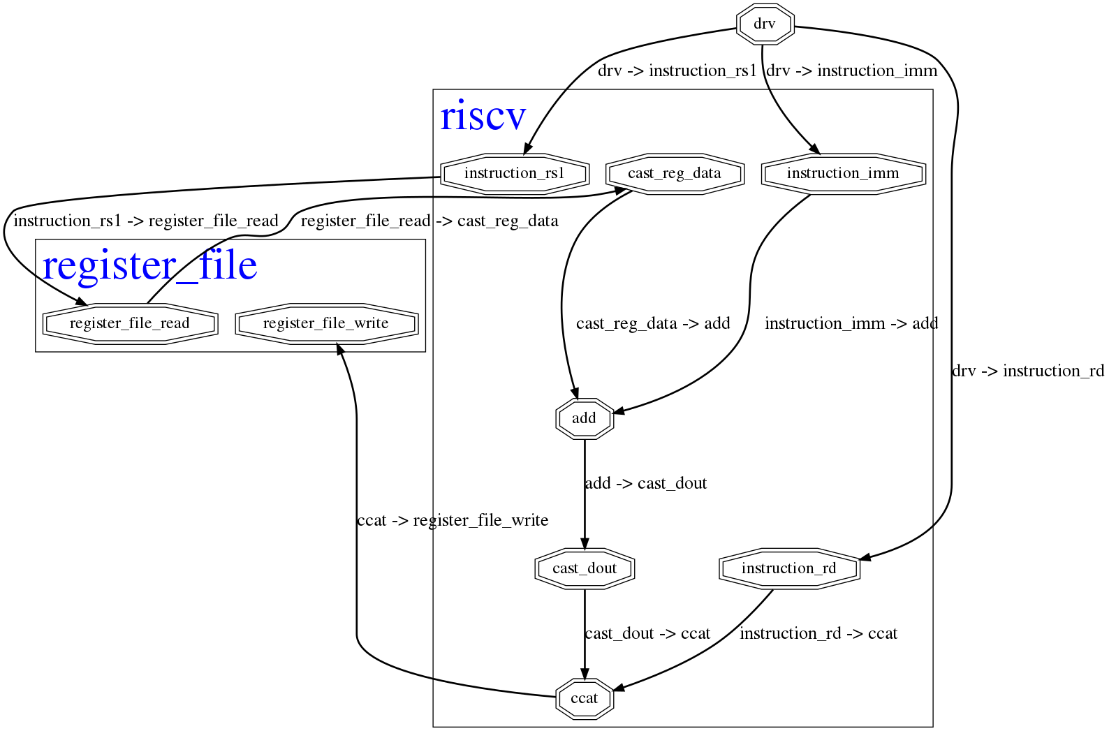
Graph of the single-instruction RISC-V processor implementation in PyGears. The gears are drown as octagons and hierarchical modules are drawn as boxes.
[Omitted long line with 1 matches]
[Omitted long line with 1 matches]
Next, data read from the register file is cast to an Int to be interpreted as a signed number: reg_data_signed = reg_data | Int[int(reg_data.dtype)]. The expression: int(reg_data.dtype) is used to retrieve the width of the reg_data interface type, and the Int type is made to be of that same width. The reg_data_signed variable carries the output signed interface of this operation This results in the cast_reg_data gear shown in the graph.
Then, the signed addition is performed between the reg_data_signed and the imm instruction field, resulting in the add gear in the graph. Finally, the addition result is cast back to the type of the reg_data interface: reg_data.dtype, which truncates the result by 1 bit and changes its type back to the unsigned integer. The interface carrying the result of these operations is stored in the variable add_res.
Next, the write request reg_file_wr_req = ccat(instruction[‘rd’], add_res) is formed, with which the register file is instructed to store the result of the addition (variable add_res) into the register specified by the rd instruction field. These two pieces of information are combined in a typing/tuple by using ccat (short for concatenation) gear from the pygears.lib library.
The read and write requests are output from the riscv gear by outputting them from the function, and will be connected to the inputs of the register file module in a higher hierarchy level.
Verification environment
For testing the ISA implementation, I’ve envisioned the following test:
Initialize the register file
Send a stream of instructions to the processor
Check the final register values to the reference design
I’ve written an environment that supports these kinds of tests in pygears_riscv/verif/env.py. This is a regular Python function (not a gear) that instantiates the riscv and register_file gears and wires them properly in the following manner.

Relevant part of the riscv_instr_seq_env() function is given below:
def riscv_instr_seq_env(instr_seq, xlen=32, reg_file_mem={}):

    instruction = drv(t=TInstructionI, seq=instr_seq)

    reg_rd_data = Intf(Uint[xlen])

    reg_file_rd_req, reg_file_wr_req = riscv(instruction, reg_rd_data)

    reg_rd_data |= \
        register_file(reg_file_rd_req, reg_file_wr_req, storage=reg_file_mem)

    return reg_file_mem
Here you can see the signature of the function and description of its parameters:
-
riscv_instr_seq_env(instr_seq, xlen=32, reg_file_mem={})¶ Drives riscv with an instruction sequence.
- Parameters:
instr_seq – Sequence of instructions to send to riscv, encoded as
TInstructionIxlen – Width of the riscv registers in bits
reg_file_mem – Initial register file dictionary that maps register IDs to their initial values
- Returns:
reg_file_mem
The drv gear can be used to drive a sequence of values to an input interface of a gear. In this case it will drive the sequence of instructions, passed via instr_seq argument: instruction = drv(t=TInstructionI, seq=instr_seq). As you can see, the t and seq arguments to the drv gear need to be specified using keywords. The reason is that PyGears needs to distinguish between gear input interfaces and gear parameters, so only input interfaces are allowed to be passed as positional arguments (without argument names).
Next, I hook up the riscv and register_file gears in the manner shown on the block diagram. You can see from the diagram that these two gears form a kind of a loop, so their connection cannot be expressed in a forward only manner. In these cases, we need to first break the loop somewhere, then connect the gears in a forward manner, and finally reconnect the loop at the point where it was broken. I decided to brake the loop at the reg_rd_data interface (as shown on the block diagram), so I explicitly instantiated the interface object with the desired type for the reg_rd_data interface: reg_rd_data = Intf(Uint[xlen]). This way we can feed it to the riscv gear, together with the instruction interface, and the riscv gear will have all the information needed to resolve itself and produce the output interfaces: reg_file_rd_req, reg_file_wr_req = riscv(instruction, reg_rd_data)
Finally, I connect riscv read and write request interfaces to the register_file gear, which gets instantiated and returns its output interface. Instead of it being fed to another gear or assigned to a variable, I use the pipe assign operator |= to instruct PyGears that this output interface is in fact the reg_rd_data interface I defined before. This closes the loop and everything is connected as shown on the block diagram.
Spike interface
In my previous blog post pygears:setup, I showed how to implement a rudimentary interface for the Spike simulator that I plan to use as a reference ISA design. Now, I’ll show how to put it to action for verifying the addi instruction implementation. I relocated the Spike interface class to pygears_riscv/verif/spike.py and had to make one major change to accomodate for the RISC-V ABI (Application Binary Interface).
First, I was surprised to find that issuing the read register command didn’t return any value in Spike simulator if the registers were named with prefix “x” (x*). I started digging and found out that even though all registers x1 - x31 were created equal in the ISA specification, in order to cooperate better with C compilers additional rules were created, namely the ABI. Chapter 20: RISC-V Assembly Programmer’s Handbook provides the table that maps the native x* register names to their ABI equivalents, and specifies special purpose for each of the registers. It turns out that the Spike simulator understands only the ABI register names. Some additional information on the ABI, together with the examples of the assembly instruction syntax, is also given on riscv/riscv-elf-psabi-doc github.
I created a wrapper class around my Spike interface inside pygears_riscv/verif/spike_instr_test.py, which automates all the tasks I did manually in the previous blog post, namely: writting the assembly file, running the gcc, and calling Spike interface with the correct parameters. I also added the possibility to easily initialize the register values which will come in handy for thourough verification.
The entry point to this Spike interface is the function run_all(), whose signature is explained below.
-
run_all(instructions, outdir='.', reg_file_init=None)¶ Runs a set of instructions on Spike simulator and returns the resulting state of the register file
- Parameters:
instructions – Sequence of instructions to execute in Spike, encoded as
TInstructionIoutdir – Directory in which to store the intermediate files
reg_file_init – Initial register file dictionary that maps register IDs to their initial values
- Returns:
The initial and the resulting state of the register file
Based on the arguments passed for instructions and reg_file_init parameters, an assembly file will be generated, which will then be compiled using gcc and finally simulated using Spike. After that, the resulting state of the register file will be read out, so that it can be compared with the results of the processor design simulation. Assembly file is generated using a following Jinja2 template:
;; # Assembly program template.

.text
  .global _start

_start:
{% for reg, value in reg_file_init.items() %}
.equ X{{ reg }}_INIT_VALUE, {{ value }}
{%- endfor %}

  ;; # Optional preloading of initial register values.
{% for reg in reg_file_init %}
  lui x{{ reg }},      %hi(X{{ reg }}_INIT_VALUE)
  addi x{{ reg }}, x{{ reg }}, %lo(X{{ reg }}_INIT_VALUE)
{%- endfor %}

  ;; # The actual instructions I'd like to test.
{% for instruction in instructions %}
  {{ disassemble(instruction) }}
{%- endfor %}

  ;; # Write the value 1 to tohost, telling Spike to quit with 0 exit code.
  li t0, 1
  la t1, tohost
  sw t0, 0(t1)

  ;; # Spin until Spike terminates the simulation.
  1: j 1b

;; # Expose tohost and fromhost to Spike so we can communicate with it.
.data
  .global tohost
tohost:   .dword 0
  .global fromhost
fromhost: .dword 0"""
Besides the boilerplate code explained in pygears:setup, there are three for loops in the template that generate the code that:
Defines a constant for each register initial value supplied via the
reg_file_initargument.Loads the constants to the registers. It requires two commands to load a 32 bit value to the register, since RISC-V instructions have fixed size of 32 bits, so they cannot contain a 32 bit immediate value besides the
opcodefield.Executes the instructions passed via the
instructionsargument. Thedissasemblefunction generates the assembly language statements from theirTInstructionIencodings.
The first idea was to use the li pseudo instruction, but I just couldn’t get it to work, and the following error kept popping up:
terminate called after throwing an instance of 'std::runtime_error'
  what():  misaligned address
So, I went with the approach described in the Absolute Addressing section of the RISC-V assembly guide.
Writing the first test
For the start, I’ll create one simple test as a proof of concept. To make it a bit more serious I’ll use negative numbers as arguments to see whether sign extension works properly too.
def test_addi():
    test_instr = ADDI.replace(imm=-1233, rd=1, rs1=1)

    reg_file_init = {1: -1}

    spike_reg_file_start, spike_reg_file_end = spike_instr_test.run_all(
        [test_instr], outdir='build', reg_file_init=reg_file_init)

    reg_file_mem = riscv_instr_seq_env(
        instr_seq=[test_instr],
        xlen=32,
        reg_file_mem=dict(enumerate(spike_reg_file_start)))

    sim()

    print(f'Resulting value of the register x1: {Int[32](reg_file_mem[1])}')

    for reg_id, reg_value in reg_file_mem.items():
        assert spike_reg_file_end[reg_id] == reg_value
In order to create the test instruction, I’ll use the ADDI template and substitute the values of the fields that I’d like to change: test_instr = ADDI.replace(imm=-1233, rd=1, rs1=1). The test_instr basically tells the processor to add a value of -1233 to the current value of the register x1 (rs=1) and store it back into the register x1 (rd=1). I’ll initialize the register x1 with the value of -1, so that both addition operands are negative: reg_file_init = {1: -1}.
First, the Spike simulator is called via run_all() function to run the test_instr, and return the referent initial and resulting states of the register file, as described in the section Spike interface.
Next, the riscv_instr_seq_env() function is called to create the verification environment, as described in the section Verification environment. The initial register file state obtained from Spike in the form of a list, is transformed to a dict and provided to the riscv_instr_seq_env() verbatim. After this statement, all the gears are instantiated and registered with PyGears framework, so when the simulator is invoked via sim(), it has all the information it needs to simulate the design. This command invokes the PyGears built-in pure-Python simulator, of which I’ll talk some more in the following blog posts.
After the simulation is done, I print the resulting value of the register x1, by casting its value to the Int[32] type in order to print its signed representation. This is of course an ptional step and is useful to me only now at the beginning for the purpose of debugging the verification environment. I’ll remove it later when I gain trust in my tests.
Finally, I check whether the resulting register file state of my design matches the state Spike reported. If the register value mismatch is found, the assert exception will be raised and the test will fail.
Running the test
For running the tests for the PyGears framework, I’ve been using pytest, so I’ll use it here too. I use a test runner since it allows me to run all my tests with a single command. It automatically searches the files in order to discover the test functions, and generates a nice report telling me how many tests passed and which of them failed. There are also options for running only a specific group of tests, run all tests from a single file or run a single test.
Before running the tests with pytest, you’ll need to install it with pip:
pip3 install pytest
In order to invoke the test with pytest, you can navigate to the tests/test_instructions folder in your terminal and run the test by invoking:
pytest "test_addi.py::test_addi"
The pytest runner should automatically find the test_addi() test function, run it and print the report:
========================================== test session starts ==========================================
platform linux -- Python 3.6.6, pytest-3.9.3, py-1.7.0, pluggy-0.8.0
rootdir: /tools/home/pygears_riscv/tests, inifile: setup.cfg
collected 1 item

test_addi.py .                                                                                    [100%]

======================================= 1 passed in 3.57 seconds ========================================
Et voila! My RISC-V design is completely aligned with the Spike simulator! By default, pytest hides all console output from the tests in order to provide a cleaner report. If I want to see the output, I need to invoke pytest with the -s option:
pytest -s "test_addi.py::test_addi"
Which prints the following:
========================================== test session starts ==========================================
platform linux -- Python 3.6.6, pytest-3.9.3, py-1.7.0, pluggy-0.8.0
rootdir: /tools/home/pygears_riscv/tests, inifile: setup.cfg
collected 1 item

test_addi.py -                      [INFO]: Running sim with seed: 6084884924426910478
0                      [INFO]: -------------- Simulation start --------------
0 /register_file/register_file_write [INFO]: Writing u32(4294966062) to x1
3                      [INFO]: ----------- Simulation done ---------------
3                      [INFO]: Elapsed: 0.00
Resulting value of the register x1: i32(-1234)
.

======================================= 1 passed in 3.58 seconds ========================================
I profiled the test a bit and found out that the majority of the test run time is spent in retrieving the register file state from Spike, so I’ll need to optimize it soon if I want to have an elaborate regression suit that runs in a reasonable amount of time.
Simulating with Verilator
One last section and I promise to let you go. I’ve written one more test in order to check whether the generated RTL code for the processor produces the correct results as well. I’ve placed the test in tests/test_instructions/test_addi.py, inside test_addi_verilator() function. The test is identical to the test_addi() described in the section Writing the first test, excepts that it set a sim_cls parameter for the riscv gear to SimVerilated: find(‘/riscv’).params[‘sim_cls’] = SimVerilated. This instructs the PyGears simulator to use Verilator interface for riscv gear, which generates the RTL code, invokes Verilator to simulate it and makes it play well with the PyGears simulator. The last bit is important since the rest of the gears (drv and register_file) will still be simulated in pure Python.
If I navigate to the tests/test_instructions directory, I can run only the test_addi_verilator() test with the following command:
pytest -s "test_addi.py::test_addi_verilator"
If there is some issue with running the Verilator, an error report will be printed, telling me which log file to check for the Verilator errors:
========================================= test session starts ==========================================
platform linux -- Python 3.6.6, pytest-3.9.3, py-1.7.0, pluggy-0.8.0
rootdir: /tools/home/pygears_riscv/tests, inifile: setup.cfg
collected 1 item

test_addi.py -                      [INFO]: Running sim with seed: 4987822489491942249
0               /riscv [INFO]: Verilating...
F

=================================== FAILURES ===================================
E           pygears.sim.modules.verilator.VerilatorCompileError: Verilator compile error: 32512. Please inspect "/tools/home/pygears_riscv/tests/test_instructions/build/riscv/verilate.log"

../../../pygears/pygears/sim/modules/verilator.py:101: VerilatorCompileError
------------------------------ Captured log call -------------------------------
sim.py                     373 INFO     Running sim with seed: 4755614176382389150
verilator.py                46 INFO     Verilating...
=========================== 1 failed in 3.89 seconds ===========================
In my case, I forgot to install Verilator and add it to the path, so my verilate.log showed that I had no verilator executable on the path, which I needed to amend:
sh: 1: verilator: not found
The test gave me an almost identical report to the pure-Python simulation. The only difference is that the simulation took longer to finish. The reason is that PyGears simulator doesn’t have a nice insight anymore into when the gears simulated in RTL are finished (think large design with a deep pipeline). The design can continue operating long after the last input has been received. PyGears works around this issue by letting the user specify the inactivity timeout after which the gear is terminated.
========================================= test session starts ==========================================
platform linux -- Python 3.6.6, pytest-3.9.3, py-1.7.0, pluggy-0.8.0
rootdir: /tools/home/pygears_riscv/tests, inifile: setup.cfg
collected 1 item

test_addi.py -                      [INFO]: Running sim with seed: 4987822489491942249
0               /riscv [INFO]: Verilating...
0               /riscv [INFO]: Done
0                      [INFO]: -------------- Simulation start --------------
0 /register_file/register_file_write [INFO]: Writing u32(4294966062) to x1
51                      [INFO]: ----------- Simulation done ---------------
51                      [INFO]: Elapsed: 0.01
Resulting value of the register x1: i32(-1234)
.
Generated SystemVerilog can be found in the /tmp folder, since no output directory was specified to the sim() function. Later, when I tidy up the tests, I’ll make it output to some reasonable destination.
module riscv(
    input logic clk,
    input logic rst,
    dti.consumer instruction, // (u7, u5, u3, u5, i12) (32)
    dti.consumer reg_data, // u32 (32)
    dti.producer reg_file_rd_req, // u5 (5)
    dti.producer reg_file_wr_req // (u5, u32) (37)

);

      dti #(.W_DATA(12)) instruction_imm_s(); // i12 (12)

      dti #(.W_DATA(33)) add_s(); // i33 (33)

      dti #(.W_DATA(32)) add_res_s(); // u32 (32)

      dti #(.W_DATA(5)) instruction_rd_s(); // u5 (5)

      dti #(.W_DATA(32)) instruction_bc[2:0](); // (u7, u5, u3, u5, i12) (32)
    bc #(
                .SIZE(2'd3)
    )
    bc_instruction (
        .clk(clk),
        .rst(rst),
        .din(instruction),
        .dout(instruction_bc)
    );


    riscv_instruction_rs1 instruction_rs1_i (
        .clk(clk),
        .rst(rst),
        .din(instruction_bc[0]),
        .dout(reg_file_rd_req)
    );


    riscv_instruction_imm instruction_imm_i (
        .clk(clk),
        .rst(rst),
        .din(instruction_bc[1]),
        .dout(instruction_imm_s)
    );


    add #(
                .DIN0(6'd32),
                .DIN0_SIGNED(1'd1),
                .DIN1(4'd12),
                .DIN1_SIGNED(1'd1)
    )
    add_i (
        .clk(clk),
        .rst(rst),
        .din0(reg_data),
        .din1(instruction_imm_s),
        .dout(add_s)
    );


    riscv_cast_dout cast_dout_i (
        .clk(clk),
        .rst(rst),
        .din(add_s),
        .dout(add_res_s)
    );


    riscv_instruction_rd instruction_rd_i (
        .clk(clk),
        .rst(rst),
        .din(instruction_bc[2]),
        .dout(instruction_rd_s)
    );


    riscv_ccat ccat_i (
        .clk(clk),
        .rst(rst),
        .din0(instruction_rd_s),
        .din1(add_res_s),
        .dout(reg_file_wr_req)
    );


endmodule
Conclusion
Hey, I have my single-instruction RISC-V processor implemented in PyGears and verified with a simple test. It may seem that much needed to happen in order for the processor to support this one instruction. But most of the effort went into building the verification environment that I think is now really powerfull and I don’t think much additional effort needs to be poured into it, besides adding the data and instruction memory modules. In fact, with only 5 lines of code, the RISC-V implementation decodes the instruction, performs the ALU operation and interfaces the register file, not bad for a 5-liner.
This post turned out longer than I expected, so I left some important topics for later blog posts like: refactoring of the tests, simulation with Cadence or Questa simulators, maximum frequency and core footprint assesment, constrained-random simulation, etc. So stay tuned!